What is a Digital Tension Gauge?
The DTG-100 is a portable digital tension gauge that measures the coupling tension between vehicle connector pins using a non-contact method.
■ Operating Principle
Detects changes in distance between Hall sensor (Hall Effect Sensor) and neodymium magnet
Measures changes in magnetic field strength to calculate tension values
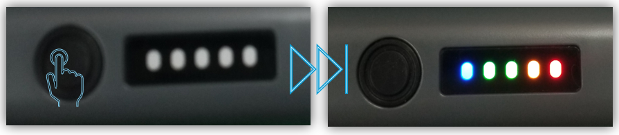
■ Display Functions
Intuitive tension level display using a 5-step LED indicator
Auditory feedback of measurement results via buzzer notification
Components
No. | Item | Quantity | Remarks |
|---|---|---|---|
1 | DTG-100 Main Unit | 1 | |
2 | Pin Adapter Set | 11 types | Detachable, according to connector specifications |
3 | USB Type-C Cable | 1 | For charging and data communication |
4 | Quick Start Guide | 1 | Brief user manual |
5 | Packaging Case | 1 | TBD |
Product Specifications
| Item | Details |
|---|---|
Measurement Method | Non-contact detection using Hall sensor |
Operating Temperature | -20°C ~ +60°C |
Charging Method | USB Type-C (5V/1A or less recommended / Under 1A Recommended) |
Charging Time | Approx. 2 hours 30 minutes (full charge) / Approx. 2.5Hrs. (Full) |
Product Size | 160(L) x 25(W) x 20(H) mm |
Product Weight | Approx. 50g |
Certifications | KC, FCC |
Digital Tension Gauge Structure
Category | Item | Description |
|---|---|---|
1 | Adapter | 11 types of replaceable pin adapters |
2 | Sensor | Non-contact differential measurement |
3 | Button | Power On/Off, Measurement |
4 | Display | 5-Level LED (Red / Orange / Green / Green / Blue) |
5 | Battery | 350mAh built-in rechargeable |
6 | Notification | Buzzer sound feedback |
7 | USB TYPE C | USB Battery Chargingㄹㄹ |
[Digital Tension Gauge] How to Use
1. Briefly press the power button
Press the power button on the main unit briefly to turn it on.
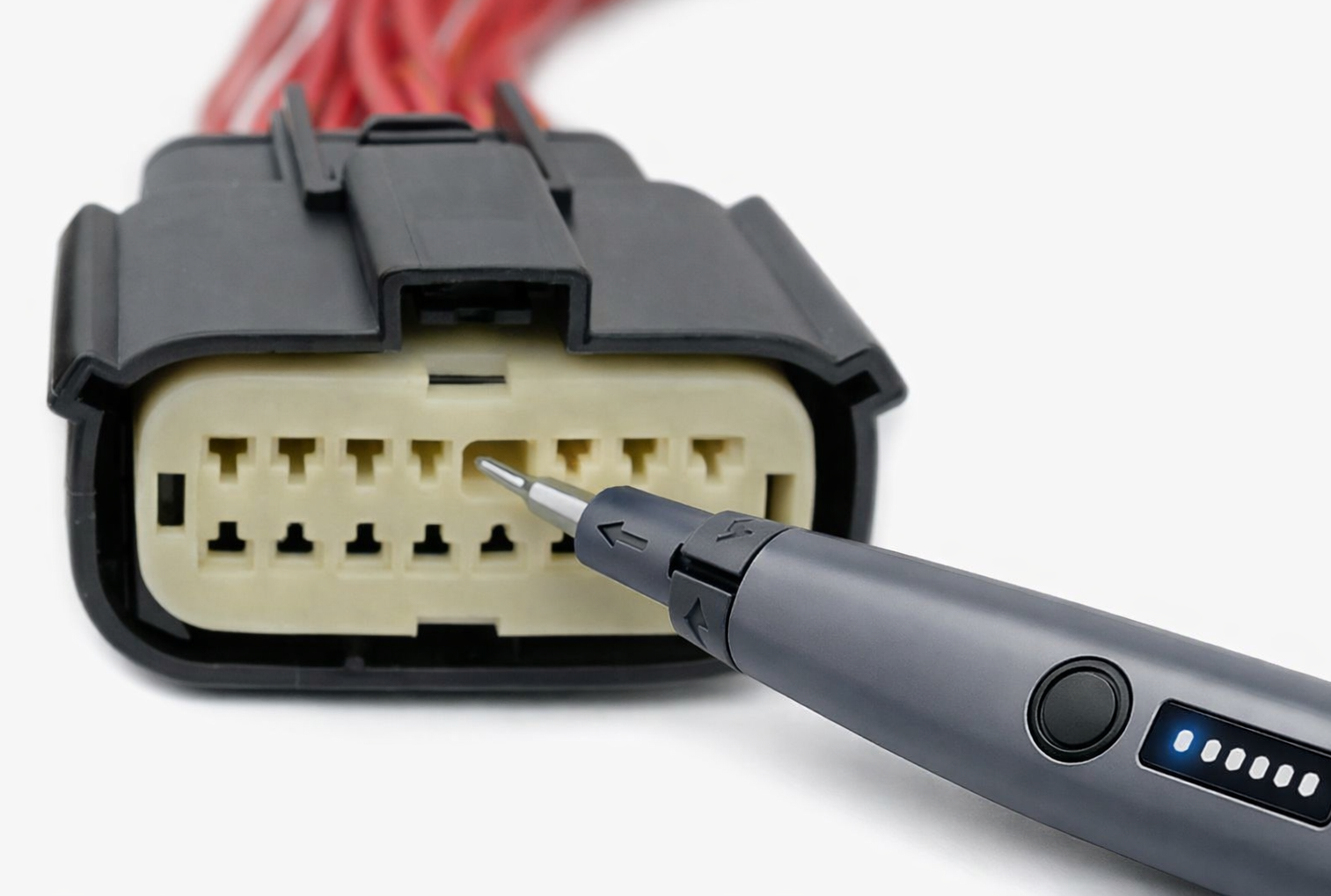
2. Attach the pin adapter
Select the appropriate pin adapter (from 11 types) for the connector to be measured and attach it to the top of the main unit.
3. Enter measurement mode
After inserting the adapter into the connector, press the button once to enter measurement mode.
- Two beeps will sound.
- Slowly pull the pin out.
4. Check measurement results
The highest reached tension level during measurement is displayed on the LED.
When complete, two beeps sound and the result LED remains lit.
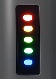
Status/Display and Notifications
📌 5-Level LED (Red / Orange / Green / Green / Blue) Display
The highest level reached during measurement is fixed and displayed on the LED.
| Level | Colour | Status | Gauge |
|---|---|---|---|
| LV1 | RED | Low | ■ □ □ □ □ |
| LV2 | ORANGE | Warning | ■ ■ □ □ □ |
| LV3 | GREEN | Standard | ■ ■ ■ □ □ |
| LV4 | GREEN | Good | ■ ■ ■ ■ □ |
| LV5 | BLUE | Optimal | ■ ■ ■ ■ ■ |
📌 Buzzer Notifications
| Status | Buzzer Notification |
|---|---|
| Power On | DO-MI-SOL-DO |
| Power Off | DO-SOL-MI-DO |
| Measurement Start | 2 beeps (beep-beep) |
| Measurement Complete | 2 beeps (beep-beep) |
| Battery Warning | Event repeats every 1 second |
📌 Battery Status & Button Operation
| Category | Description |
|---|---|
| Battery Status | Battery level LED displayed when power ON (5 levels) |
| Charging: LED blinks | |
| Charging complete: LED off | |
| Below 30%: buzzer warning | |
| Button Operation | Short press (< 1.5s): Power ON / Start measurement / Re-measure |
| Long press (≥ 1.5s): Power OFF |
📌 Pin Adapter Specifications
The pin adapter shall be set and used in accordance with the specifications specified in the GSW (Global Service Way) maintenance manual. These specifications serve as standards to ensure equipment safety and performance, and therefore must be applied as instructed in the manual.
| Size | Widt (mm) | Features & Typical Applications | Color |
|---|---|---|---|
| 020 | 0.51 mm | Ultra-small automotive connector pin | RED |
| 025 | 0.64 mm | Standard small automotive electrical connector | BLUE |
| 030 | 0.76 mm | Ultra-small sensor connector | WHITE |
| 040 | 1.02 mm | Small signal connector | YELLOW |
| 050 | 1.27 mm | Signal connector | PINK |
| 060 | 1.52 mm | Medium signal connector | SKY BLUE |
| 070 | 1.78 mm | Automotive multi-pin connector | BLACK |
| 080 | 2.03 mm | Medium connector | VLOLET |
| 120 | 3.05 mm | Medium-current connector | GRAY |
| 187 | 4.75 mm | Standard quick connect (flat tab) – 4.8 mm | GREEN |
| 020 | 6.35 mm | Standard quick connect (flat tab) – 6.3 mm | ORANGE |
📖 Special Appendix - FAQ
1. Power does not turn on
- Charge for more than 30 minutes with USB cable and retry
- Power automatically turns off when battery is low.
2. LED does not change during measurement
- Check if the adapter is properly attached
- Pull the pin slowly and steadily during insertion/removal.
3. Measurement values are unstable
- Remove strong magnetic field sources nearby.
- Keep the product stable before starting measurement.
4. Automatic shutdown after 5 minutes
- This is normal operation.
- Automatic power off function to save battery (if no operation for 5 minutes)
5. Repeated warning buzzer
- Battery level below 30%. Please charge immediately.
- Forced power off when battery is insufficient.
Warranty |
This product has been manufactured through strict quality control and inspection processes.
GIT provides product warranty as below in accordance with consumer protection laws.
Please contact the point of purchase or our headquarters if product failure occurs.
Product Name | ||||
S/No. | Purchase Date | |||
Place of Purchase | Business Name | Name | ||
Contact | Warranty Period | Refer to 'b. Warranty Period by Item' | ||
Warranty service
Free service is available only if failure occurs under normal use within the product warranty period after purchase.
If the purchase date cannot be confirmed, the warranty period is calculated as 1 year + 3 months (product distribution period) from the date of shipment from headquarters.
Compensation Criteria
a. Compensation Criteria by Type
Type | Within Warranty Period | After Warranty Period |
| Repair required within 14 days of purchase | Product exchange | Not applicable |
| Failure during normal use | Free repair | Paid repair |
| If the same part fails more than 3 times | Product exchange | Paid repair |
| If repair is not possible due to lack of parts within parts retention period | Handling our company regulations | |
b. Warranty Period by Item
Category | Type | At initial set purchase | When purchased individually | Re-warranty after repair |
Main Unit | Failure during normal use | Compliance with applicable countrie's A/S regulations | ||
Accessories | 1 year | 6 months | Not applicable | |
Others | Compliance with applicable countrie's A/S regulations | |||
c. Item Classification
Category | Item |
Main Unit |
|
Accessories |
|
Consumables |
|
Others |
|
* The above items include optional items, and the components may differ depending on the optional items selected.
* For optional items additionally developed by our company in the future, please refer to the website (www.gitauto.com).
Paid Service
Please check the product warranty contents carefully as the following cases will incur service charges.
| ▼ Cases that are not malfunctions |
| - Service requests due to customer's operation errors |
| - Simple adjustments without disassembling the product or explanations of product functions |
| - Requests for program updates |
| ▼ Failures caused by consumer negligence |
| - Failures due to careless handling by the consumer (drops, shocks, breakage, excessive operation, etc.) |
| - Failures caused by using unspecified power sources |
| - Failures caused by modifications or repairs by third parties other than those designated by us |
| - Failures and damages caused by use of parts other than those specified by us |
| - Failures and damages caused by arbitrary changes/modifications of diagnostic cables, adapters, etc. |
| ▼ Other cases |
| - Failures and damages due to natural disasters (fire, salt damage, flood, etc.) |
| - Consumable parts reaching end of life (battery, etc.) |
Other Matters
- The retention period for A/S parts is 5 years from the product discontinuation date.
- When purchasing the entire product (SET), exchanges are made for each individual device.
Automotive diagnosis and repair methods should ultimately be decided based on the user's judgment, and manufacturers and sellers are not responsible for the results of diagnosis and repair methods.